WeekendPrj: 32by16 RGB Panel Control with ZYNQ APSoC(2017)
Introduction
RGB LED matrix panels are mostly used to make video walls. Due to its circuit design, one will need use propper controlled PWM wave for displaying full color on it. Micro Controllers like ARDUINO cannot afford the computation power to drive such type of LED panel especially when the amount of LEDs increase. In this project, I use ZYNQ all programmable SoC for controlling the RGB LED matrix, with the FGPA on the ZYNQ, logic on FPGA schematic can read 24 bit RGB data from BRAM and drive the LED panel with PWM wave. ARM processor on the ZYNQ can control the image displayed by changing the BRAM content using an AXI-lite BRAM controller.
This is a one weekend hobby project I have done in Spring 2017 and ledctrl.vhd code is referenced from ADAFRUIT.
LED Panel Design & FPGA code to drive it
This 32by16 LED Panel is bought from ADAFRUIT.
From Adafruit, there is a tutorial explaining how it works and how to drive it with arduino or raspberry pi.
There is a very nice tutorial exlaining about how LED panel works and how LED controller on FPGA works. https://bikerglen.com/projects/lighting/led-panel-1up/
Since these tutorials have described it very clearly, I ll avoid re-presenting these tutorials.
Top Level FPGA Block Diagram
The following diagram is the diagram plotted in VIVADO ip-integrator. VIVADO ip-integrator is my favorate tool for system design, especially when dealing with ZYNQ SoC similar systems. If you are working with ZYNQ SoC, there is no other option for designing system other than VIVADO ip-integrator since ISE is nolonger supported. With VIVADO ip-integrator, you can design your system with a nice GUI as it shown in the following figure. With pure FPGA system design, VIVADO ip-integrator will also help to make your design clean and easy to understand.
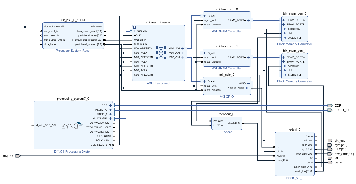
Figure 1. Vivado Ip Integrator Block Diagram.
To get a better understand of the system diagram. I plotted the following system diagram in Microsoft Visio. In ZYNQ SoC, the ARM processor is the main controller of everything. It controls the FPGA devices through AXI-lite interface. It is a type of BUS protocol from ARM community. Two BRAMs are used to generate the higher and lower section of the memory for the LED panel. BRAM controllers are used to allow ARM processor to take full controll of the LED panel. DIV[7:0] are used to controll the refresh rate of the led panel and is connected to the switches on the ZedBoard. Rst is implemented by using AXI-GPIO ipcore from XILINX. This allows for software reset from ARM processor.
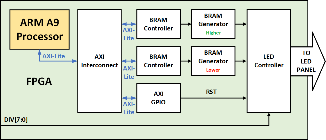
Figure 2. System Block Diagram.
The interface of the system is done through the FPGA I/Os. The controll signals are connected from the LED panel to the PMOD connectors on the ZedBoard. Details can be found in teh contraint.xdc file. The div[7:0] is connected to the switches on the ZedBoard.
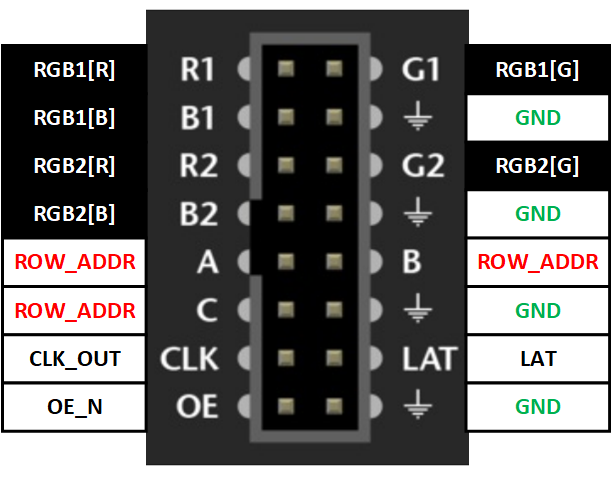
Figure 3. RGB Panel Connector Interface.
Two BRAM Generators are used to generate the upper half and lower half memory of the LED panel. In the VIVADO ip-integrator, I pre-filled the upper BRAM with data 0x00ff0000, and the lower BRAM with data 0x000000ff. Once I program the FPGA on the Zynq and PS7_INIT.TCL is excecuted to start giving clk to the FPGA. The upper half of the LED panel will be filled with color blue and the lower half of the LED panel will be filled with green. I ll further talk about how to change the BRAM though ARM processors on ZYNQ.
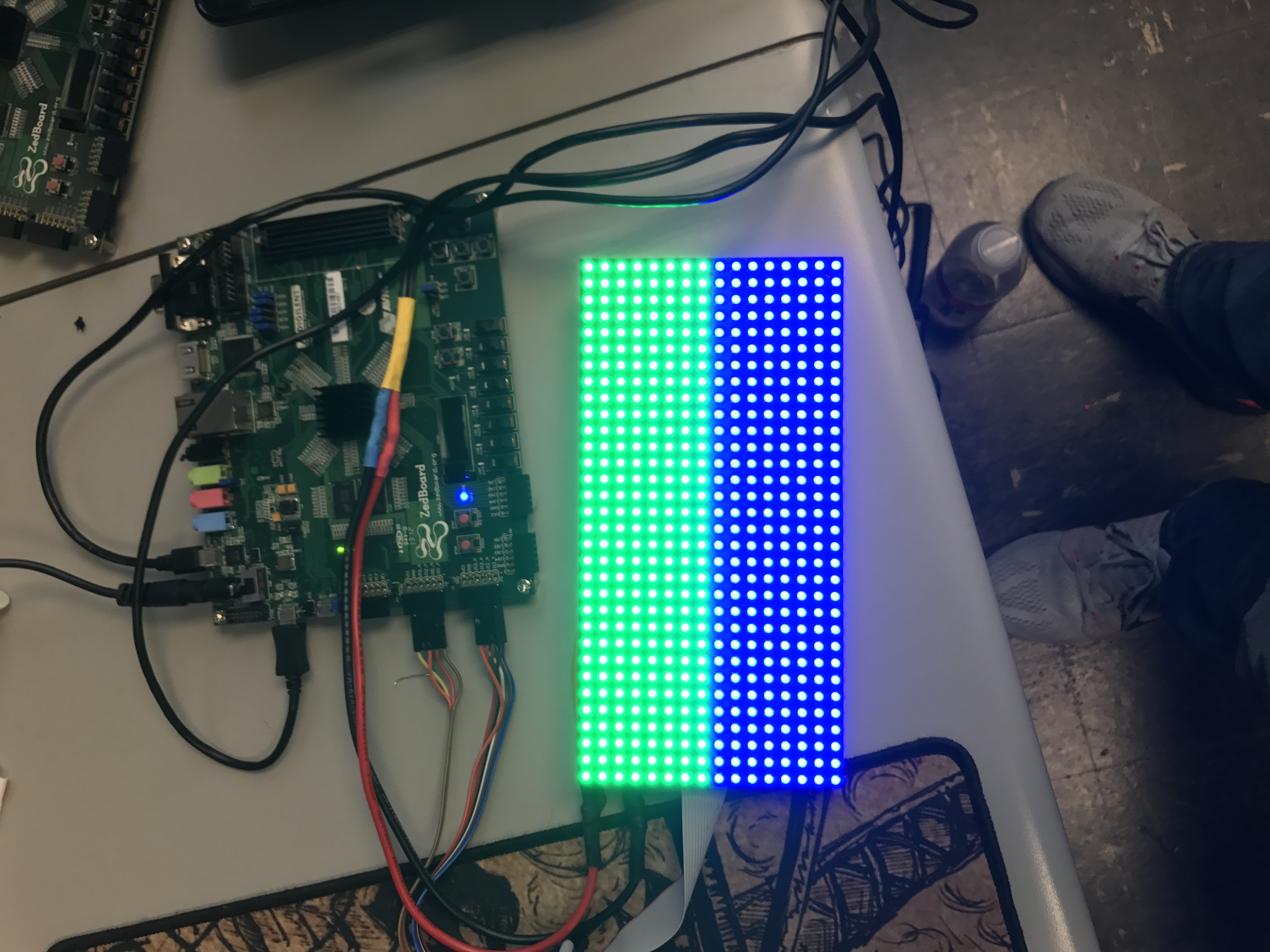
Figure 4. Initial test result with solid colors.
Write Software in XSDK
A simple C code for ARM processor is written to test the circuit:
#include <stdio.h>
#include "platform.h"
#include "xil_io.h"
#include "xil_printf.h"
u32 upper_array[256] = {

        0x1000d,0x1000e,0x1010f,0x1000f,0xf,0x2010f,0xa080d,0x100e0b,0xe0d0c,0x6050e,0xf,0x10010,0x10010,0x10010,0x10010,0x10010,0x10010,0x1000f,0x1010f,0x1010e,0x1000e,0x1000d,0x1000d,0x1000c,0x1000c,0x0,0x0,0x0,0x0,0x0,0x0,0x0,0x1000e,0x1000e,0x1000f,0x1000f,0x151309,0x252608,0x212810,0x1b2616,0x1d2614,0x26290b,0x1f1e07,0x4030e,0x10,0x10010,0x10010,0x10010,0x10010,0x10010,0x10010,0x1000f,0x1000e,0x1000e,0x1000d,0x1000d,0x1000c,0x0,0x0,0x0,0x0,0x0,0x0,0x0,0x1000e,0x1000f,0x1000f,0x1c1c09,0x192417,0x31c2b,0x1b2e,0x1b2e,0x1b2e,0x1b2e,0x14231c,0x272706,0x4040f,0x11,0x10,0xf,0xf,0x10,0x10010,0x1000f,0x1000f,0x1000e,0x1000d,0x1000d,0x1000d,0x0,0x0,0x0,0x0,0x0,0x0,0x0,0x1010e,0xe,0x161509,0x172319,0x1a2e,0x1c2f,0x1c2f,0x1c2f,0x1c2f,0x91a22,0x6111e,0x12211d,0x222107,0xf,0xe0d0c,0x1d1c08,0x1a1808,0xc0a0c,0x10,0xf,0x1010f,0x1010e,0xd,0x1000d,0x1000d,0x0,0x0,0x0,0x0,0x0,0x0,0x0,0xf,0x100f0b,0x2e2e06,0x31a29,0x1c2f,0x1c30,0x1c30,0x1d30,0x1d30,0x31626,0x51220,0x182c,0x222810,0xf0e0b,0x292906,0x14211b,0x13221d,0x25290d,0x1d1c08,0x1c1b08,0x252508,0x252608,0x1c1b07,0x3020c,0x2010d,0x0,0x0,0x0,0x0,0x0,0x0,0x0,0xe,0x212007,0x1f2410,0x1a2f,0x1b2f,0x11827,0x31623,0x41324,0x81620,0x1c2514,0x51d29,0x1b2f,0xe2021,0x1e1d07,0x191808,0x12211e,0x1a2f,0x11a2c,0x20250f,0x171e14,0x41b29,0x21a2b,0x252b0f,0x100f09,0xd0c0a,0x0,0x0,0x0,0x0,0x0,0x0,0x0,0xe,0x1e1d08,0x111d1b,0xf0f0c,0x3013da,0x1815ea,0x21506,0x12010d,0x2101f9,0x2c14f8,0xf1b1c,0x1c30,0x21b2c,0x242609,0x1c1a06,0x12211e,0x1b2f,0x1c2f,0x11629,0x192d,0x1c2f,0x10201f,0x242306,0x3010c,0x2010c,0x0,0x0,0x0,0x0,0x0,0x0,0x0,0xf,0x16170c,0x2817f5,0x29ffd6,0x4116bf,0x3119cf,0x1c02,0xd090b,0x1c0003,0x2bffeb,0x1c0600,0x1b2e,0x1b2f,0x172218,0x312e00,0x15221a,0x1b2f,0x1c2f,0x1c2f,0x1c2f,0x1b2e,0x25280b,0x7070c,0xd,0xd,0x0,0x0,0x0,0x0,0x0,0x0,0x0

};
u32 lower_array[256] = {

        0xf,0x7070f,0x2b2601,0x2801dd,0x370ec9,0x411dbf,0x121cf0,0x31808,0x15030b,0x2501f6,0x2f00e9,0xf1015,0x1d30,0x11a2c,0x252b0e,0x2f3007,0x41726,0x11729,0x1c2f,0x1c2f,0xb1e24,0x232206,0xd,0x1000d,0x1000d,0x0,0x0,0x0,0x0,0x0,0x0,0x0,0x1000f,0xf,0x15170c,0x2c1af4,0x3001d0,0x401cc0,0x3420cd,0x22002,0xb100a,0x1b0206,0x2c01ee,0x2603f5,0x31929,0x1e31,0x1172a,0xd1c1f,0x71722,0x192c,0x192c,0x41c2a,0x24290e,0x100f09,0xe,0x1000d,0x1000d,0x0,0x0,0x0,0x0,0x0,0x0,0x0,0x1000f,0x10010,0x10110,0x272708,0x2203ec,0x390bc7,0x4324bd,0x2422de,0x2107,0x110c0a,0x200301,0x3001ea,0x1e07ff,0x11729,0x1b2e,0x11427,0x182c,0x61c27,0x24260b,0x232409,0x12110a,0xe,0x1000e,0x1000d,0x1000d,0x0,0x0,0x0,0x0,0x0,0x0,0x0,0x1010e,0x10,0xc0b0c,0x23290e,0x30b1c,0x21ffe7,0x3c10c4,0x4228be,0x1d26e6,0x1220a,0x140c09,0x2303ff,0x3102ea,0x2204f8,0xb0a13,0x50b1b,0x71520,0x262a0c,0x12100a,0x10,0xf,0x1000e,0x1000e,0x1000d,0x1000d,0x0,0x0,0x0,0x0,0x0,0x0,0x0,0x1000e,0x3020e,0x2a2a06,0xc1d22,0xb151c,0x242208,0x3115ea,0x3a11c8,0x4128bf,0x212ae2,0x2260a,0x121309,0x2305ff,0x3103ec,0x3003eb,0x2715ff,0x282807,0x100f0b,0x10,0x10010,0x1010f,0x1000e,0x1000e,0x1000d,0x1000d,0x0,0x0,0x0,0x0,0x0,0x0,0x0,0x1000e,0x2020e,0x1f1f08,0x24260a,0x222208,0xf0f0c,0x191b0c,0x2e22fc,0x351ce2,0x3c28cc,0x282bdf,0x72b07,0x121d0a,0x271702,0x2d2501,0x1f1e08,0x6050e,0x10,0x10010,0x1000f,0x1010f,0x1000e,0x1000d,0x1000d,0x1000d,0x0,0x0,0x0,0x0,0x0,0x0,0x0,0x1000e,0x1000e,0x1000e,0x2010f,0x10,0x10,0xf,0x70810,0x18190d,0x242306,0x2a2700,0x262704,0x212308,0x18190a,0x8080e,0xf,0x11,0x10010,0x1000f,0x1010f,0x1000e,0x1000e,0x1000d,0x1000c,0x1000c,0x0,0x0,0x0,0x0,0x0,0x0,0x0,0x1000d,0x1000e,0x1010e,0x1000f,0x1000f,0x10010,0x10010,0x10,0xe,0xf,0x12,0x10010,0xf,0xe,0x10,0x10010,0x10010,0x1000f,0x1010f,0x1010e,0x1000e,0x1000d,0x1000d,0x1000c,0x1000c,0x0,0x0,0x0,0x0,0x0,0x0,0x0

};
int main()
{
    init_platform();
    u32 baseaddr = 0x40000000;
    u32 highaddr = 0x41000000;
    int i=0;
    for(i=0;i<256;i++)
    {
        Xil_Out32(highaddr+4*i,upper_array[i]);
        Xil_Out32(baseaddr+4*i,lower_array[i]);
    }
    cleanup_platform();
    return 0;
}
Test Results
The first test case I wrote here is to use a for loop to write incrementing numbers to fill the BRAM memoery. The code split the screen into 4 sections and displaying 4 different colors(RGBW) in different intensity.
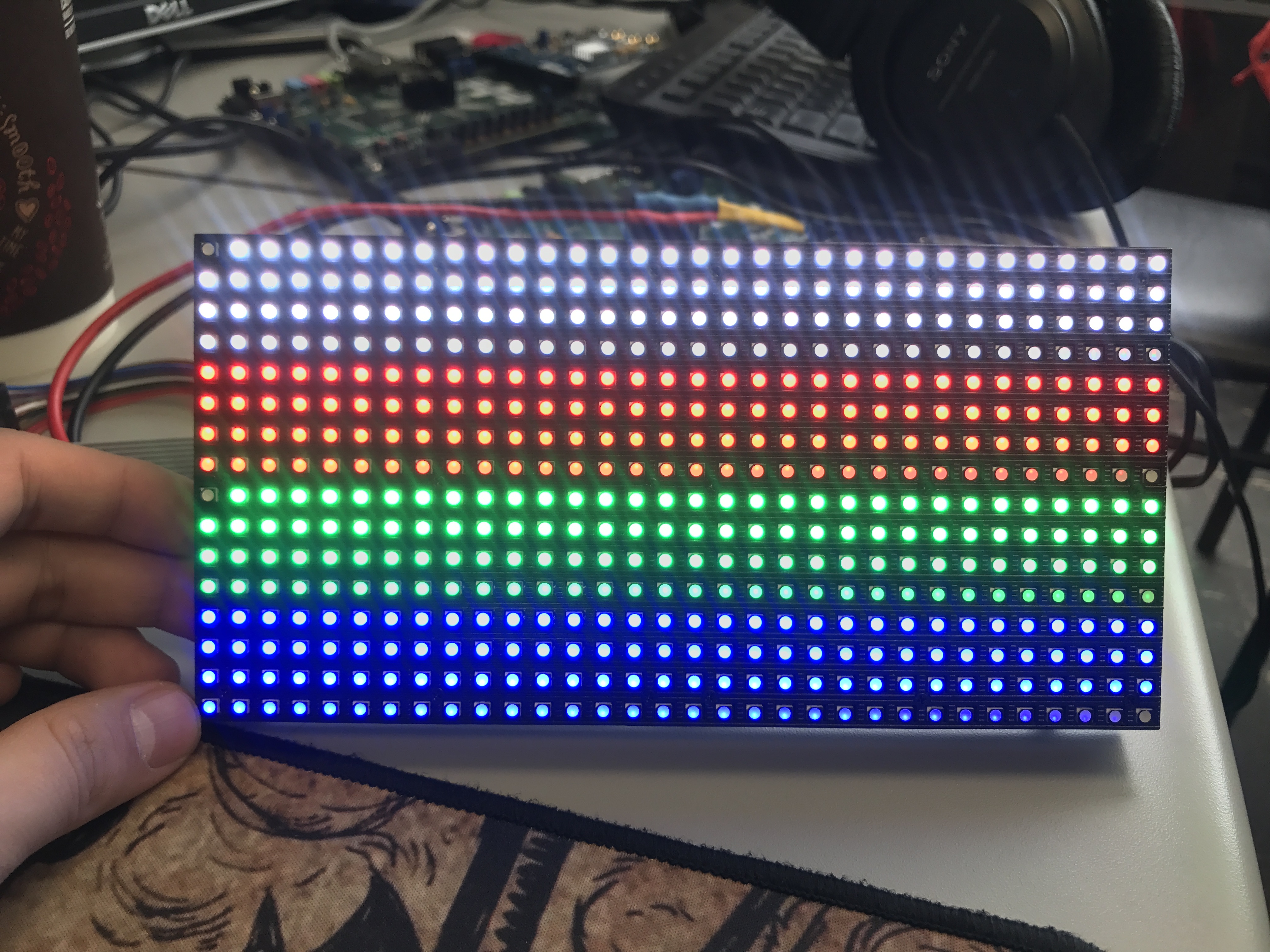
Figure 5. True Color Test Result
A MATLAB code is written to read RGB image and generate the input figure for the LED panel. In MATLAB, I read the image file using imread function and manually decimate the figure to 32by16 pixels. The generated data is feed to the code written in XSDK. Software running on ARM processor will take the data and transmit it to BRAM through BRAM controller using AXI-Lite interface. The resolution of 32x16 is not enough to display this whale, which makes the final result look weird.
Figure 6. Whale Picture
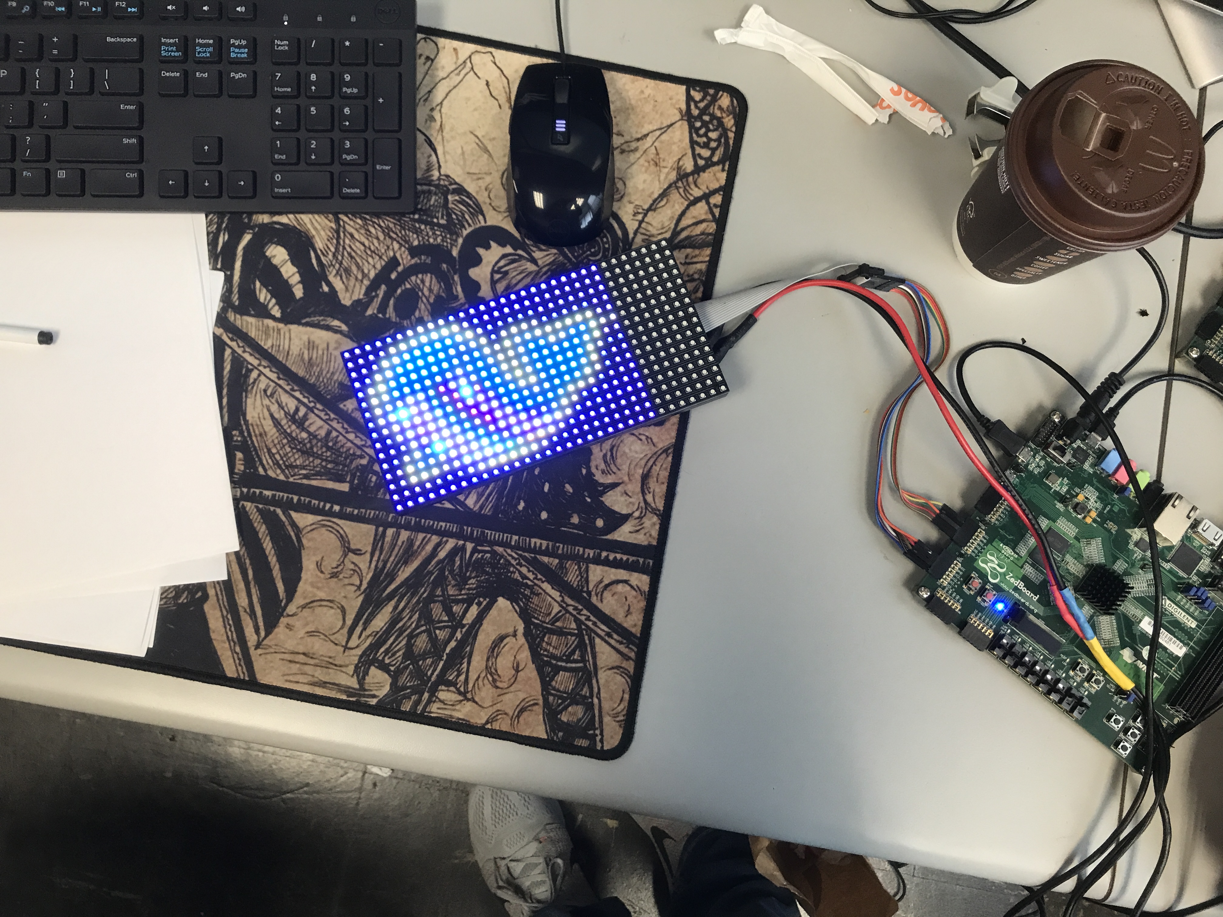
Figure 7. Whale Picture Diplayed on the Panel
Project Expansion
In Summer 2019, three students in summer project shows interests in this project and expand it from one LED panel to six. With six panels, they were able to show decent pictures on the panel. Figure 8 shows the finished project with Mona Lisa displayed on the panel.
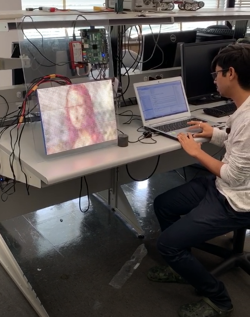
Figure 8. Students working with 6 LED Panels controlled by ZYNQ APSoC
With their hardware setup, I implemented camera -> python -> zedboard datapath as shown in Figure 9. The python code read the data from the camera and downsample it in order to transmit it to the LED Panel, the image data is transmitted through serial link at 115200 BaudRate, with a very limited refresh rate.
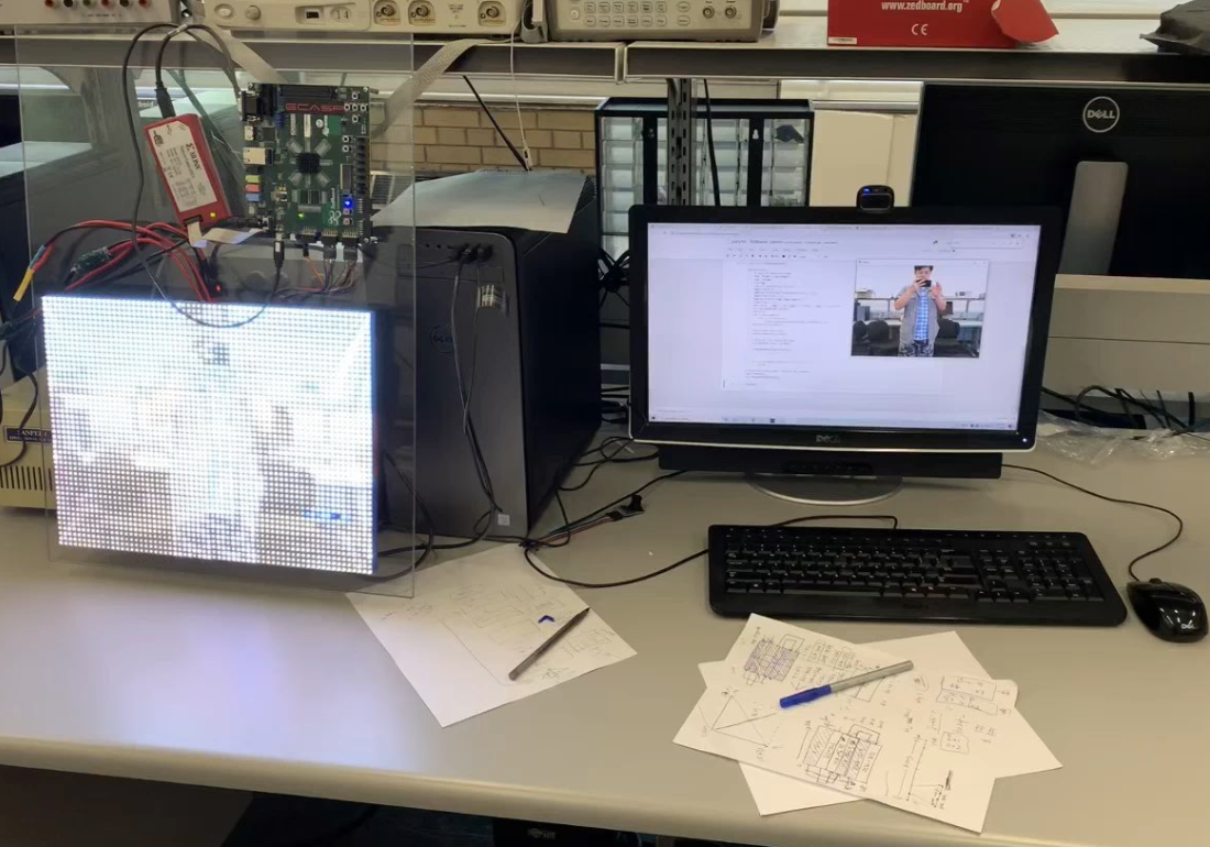
Figure 9. Image -> Camera -> Computer -> Zedboard Data Path
In order to synchronize image frame between Python code on computer and C code on ZYNQ APSoC, I implemented a simple signal mechanism. As shown in the following code:
def setmode(char):
   serzed = serial.Serial(
               port= 'COM6',\
               baudrate=115200,\
               parity=serial.PARITY_NONE,\
               stopbits=serial.STOPBITS_ONE,\
               bytesize=serial.EIGHTBITS,\
                  timeout=0)
   serzed.write(bytes(char,encoding='utf-8'))
   serzed.close()

def padded_hex(i, l):
   given_int = i
   given_len = l

   hex_result = hex(given_int)[2:] # remove '0x' from beginning of str
   num_hex_chars = len(hex_result)
   extra_zeros = '0' * (given_len - num_hex_chars) # may not get used..

   return ('0x' + hex_result if num_hex_chars == given_len else
            '?' * given_len if num_hex_chars > given_len else
            '0x' + extra_zeros + hex_result if num_hex_chars < given_len else
            None)

def transmitdata(data):
   serzed = serial.Serial(
               port= 'COM6',\
               baudrate=115200,\
               parity=serial.PARITY_NONE,\
               stopbits=serial.STOPBITS_ONE,\
               bytesize=serial.EIGHTBITS,\
                  timeout=0)

   serzed.write(bytes('z',encoding='utf-8'))

   for i in data:
      if len(i) == 8:
            serzed.write(bytes(i[2],encoding='utf-8'))
            serzed.write(bytes(i[3],encoding='utf-8'))
            serzed.write(bytes(i[4],encoding='utf-8'))
            serzed.write(bytes(i[5],encoding='utf-8'))
            serzed.write(bytes(i[6],encoding='utf-8'))
            serzed.write(bytes(i[7],encoding='utf-8'))
   serzed.write(bytes('!',encoding='utf-8'))
   serzed.close()
With the following code, the Python code will repeatedly read image from camera and transmit it to the ZYNQ APSoC until we manually terminate it:
cap = cv2.VideoCapture(0)
while(True):
   # Capture frame-by-frame
   ret, frame = cap.read()
   img = frame
   crp=img
   crp=cv2.resize(crp,(64,48))
   img1=crp[0:16,:,:]
   img2=np.fliplr(np.flipud(crp[16:32,:,:]))
   img3=crp[32:48,:,:]
   img=np.hstack((img3,img2,img1))
   rede=crp[:,:,2]
   dec_value = img[:,:,0] +img[:,:,1]*256 + img[:,:,2]*65536
   r,c=np.shape(dec_value)
   hexvv=[]
   for i in range(r):
      for j in range(c):
            hexvv.append(padded_hex(dec_value[i,j],6))
   asciiio=ascii(hexvv)

   hexvv1=hexvv[0:1536]
   hexvv2=hexvv[1536:3072]

   # Display the resulting frame
   cv2.imshow('frame',frame)
   transmitdata(hexvv2+hexvv1)
   if cv2.waitKey(1) & 0xFF == ord('q'):
      break

# When everything done, release the camera
cap.release()
cv2.destroyAllWindows()
To duplicate the design
There are too many files in the VIVADO project, so I didn’t upload it in the GitHub. Instead, I generated a TCL file: system_diagram_gen.tcl to help you build your own VIVADO project. Before you run this TCL file, you need to modify the project’s path to put your project and the path for the ipcore as well. After building the block diagram, you will have to manually link the constraint file since I didn’t include that part in my TCL file. The ARM processor’s software is included in the folder XSDK_SW The image here should be a whale in Figure 6.